![]()
![]()
![]()
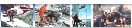
![]() SAR Technology: 'Incident
Commander Pro' Software
SAR Technology: 'Incident
Commander Pro' Software
![]() Displaying GIS CAD files
in 'Incident Commander Pro'
Displaying GIS CAD files
in 'Incident Commander Pro'
 'Incident Commander Pro'
can display many common file types as map layers within it's GIS module. These
file types including shape-files,
coverages, tif, gif, jpg, bmp and MrSID images .
'Incident Commander Pro'
can display many common file types as map layers within it's GIS module. These
file types including shape-files,
coverages, tif, gif, jpg, bmp and MrSID images .
'Incident Commander Pro'
also has the capability to display the vector-based .DXF and .DWG CAD drawing
files.
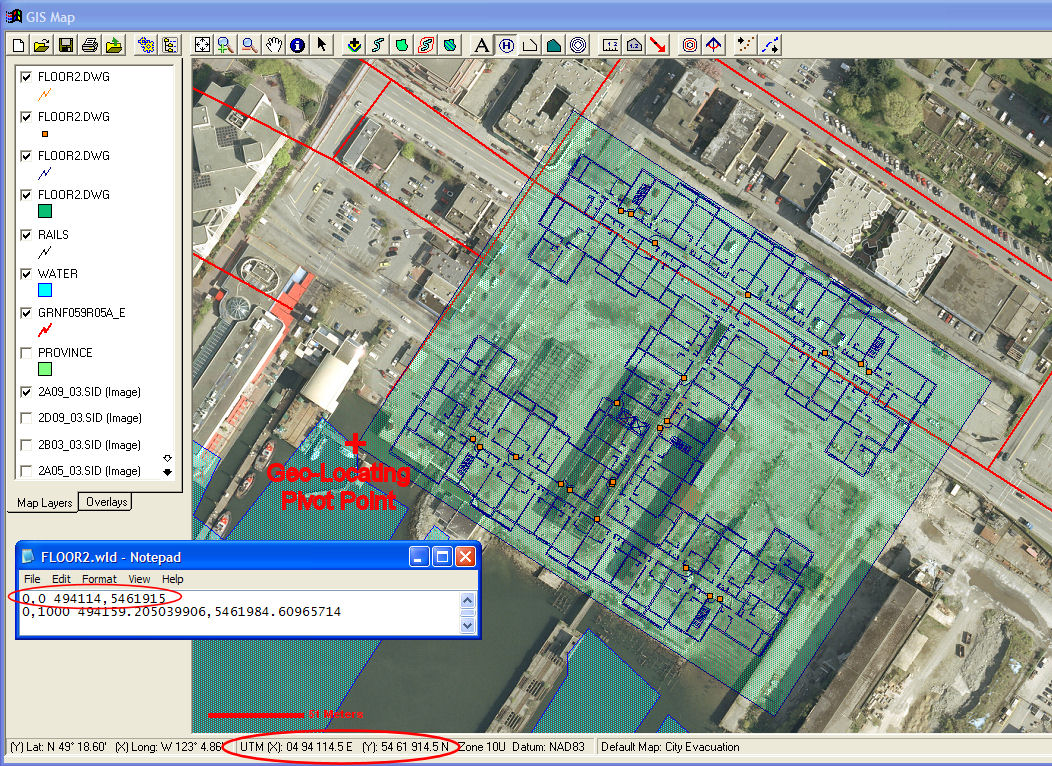
Being able to display DWG and DXF files provides the unique opportunity to review geo-located buildings and site-plans - such as stadiums, conference centers, airports, public utilities, dams, power stations and other critical infrastructures - within the ''Incident Commander Pro' GIS module. These CAD file types are displayed as true engineering drawings, with all of their associated properties - for example color, line-size, labels etc. - available for fully customizable display by 'Incident Commander Pro'.
|
|
CAD building floor plan
FLOOR2.dwg |
![]() 'Incident Commander Pro'
can
directly display DWG and DXF CAD files by simply loading these files as map layers,
using the GIS module's
'Incident Commander Pro'
can
directly display DWG and DXF CAD files by simply loading these files as map layers,
using the GIS module's ![]() 'Add Map Layers' button.
'Add Map Layers' button.
![]() To take full advantage of these
CAD files it is also possible to Geo-Locate, Scale and Rotate these engineering
drawings,
so that they are correctly displayed in relation to the other geographic map
layers. This is accomplished by creating a small companion text 'World
File', that provides the drawing's location, scale and rotation to the GIS map
display.
To take full advantage of these
CAD files it is also possible to Geo-Locate, Scale and Rotate these engineering
drawings,
so that they are correctly displayed in relation to the other geographic map
layers. This is accomplished by creating a small companion text 'World
File', that provides the drawing's location, scale and rotation to the GIS map
display.
![]() To
create the small .wld 'World File' enter the required Location ie UTM Easting
& Northing , Scale Factor and Rotation Angle into CAD_MapLocator.xls.
Paste the output values into a text file with the same name as the CAD file, but
with the .wld extension eg: for SitePlan.dwg or
SitePlan.dxf paste the output values into SitePlan.wld.
With this text 'World File' in the same directory as the .dwg or .dxf CAD
file, the CAD drawings will be correctly geo-located, scaled and rotated when
added to the GIS module, using the
To
create the small .wld 'World File' enter the required Location ie UTM Easting
& Northing , Scale Factor and Rotation Angle into CAD_MapLocator.xls.
Paste the output values into a text file with the same name as the CAD file, but
with the .wld extension eg: for SitePlan.dwg or
SitePlan.dxf paste the output values into SitePlan.wld.
With this text 'World File' in the same directory as the .dwg or .dxf CAD
file, the CAD drawings will be correctly geo-located, scaled and rotated when
added to the GIS module, using the
![]() 'Add Map Layers' button.
'Add Map Layers' button.
![]() Once
the CAD file is displayed in 'Incident Commander
Pro' it's color, transparency, symbols, labels,
text and other engineering data can be fully customized by adjusting the
drawing's map layer properties.
Once
the CAD file is displayed in 'Incident Commander
Pro' it's color, transparency, symbols, labels,
text and other engineering data can be fully customized by adjusting the
drawing's map layer properties.
![]() SAR
Technology Inc.
SAR
Technology Inc.
5268 Sprucefeild Road, West Vancouver
B.C., Canada V7W 2X6
![]() Phone:
(604) 590-7419 / (604) 921-2488
Phone:
(604) 590-7419 / (604) 921-2488  Fax (604) 921-2484
![]() Go Back to SAR Technology
Home Page
Go Back to SAR Technology
Home Page